What are the Methods to Ensure Assembly Accuracy?
What are the methods of calculating the positioning error?
Positioning error in two aspects:
1. The positioning error caused by the inaccuracy of the workpiece positioning surface or the positioning element on the fixture is called the reference position error.
2. The positioning error caused by the process datum and positioning datum of the workpiece is called datum mismatch error.
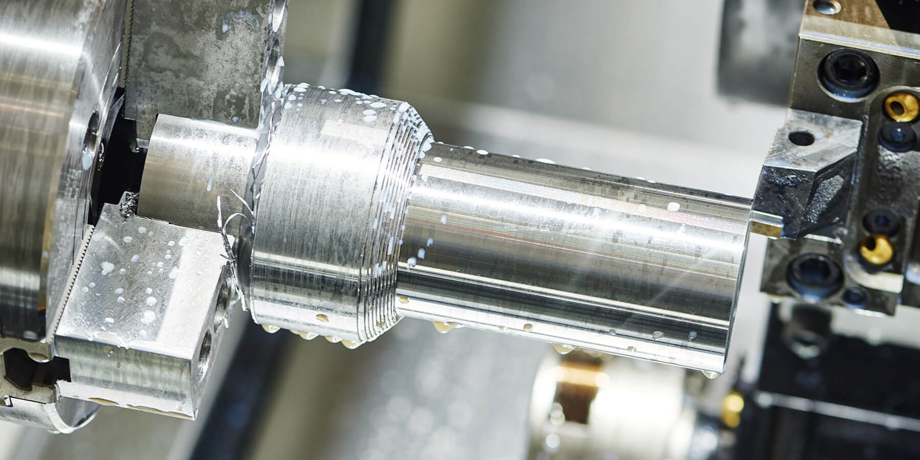
Basic requirements for the design of workpiece clamping device.
1. In the process of clamping should be able to maintain the workpiece positioning obtained by the correct position.
2. The size of the clamping force is appropriate, the clamping mechanism should be able to ensure that the workpiece does not produce loose or vibration in the process of processing, but also to avoid improper deformation and surface damage to the workpiece, the clamping mechanism should generally be self-locking
3. The clamping device should be easy to operate, labor-saving and safe. 4. The complexity and automation of the clamping device shall be commensurate with the production volume and production mode. The structural design should be simple, compact and adopt standardized components as far as possible.
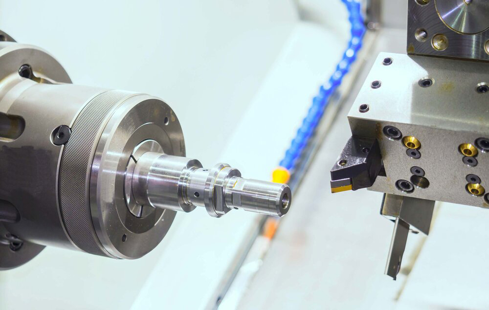
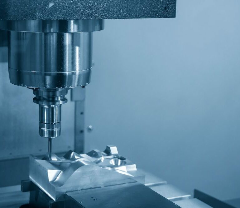
Three elements to determine the clamping force? What are the principles for choosing the direction and point of clamping force?
The choice of clamping force direction of the size direction should generally follow the following principles:
1. The direction of the clamping force should be conducive to the accurate positioning of the workpiece, without destroying the positioning, so the general requirement is that the main clamping force is perpendicular to the positioning surface
2. The direction of the clamping force should be consistent with the direction of the large stiffness of the workpiece as far as possible to reduce the workpiece clamping deformation
3. The direction of the clamping force should be as much as possible with the cutting force, the workpiece gravity direction, in order to reduce the required clamping force clamping force point selection of general principles:
1) the clamping force point should be on the supporting surface formed by the supporting element, to ensure that the workpiece has been fixed positioning
2) the clamping force should be in the position of good rigidity to reduce the workpiece clamping deformation
3) the clamping force should be close to the machining surface as far as possible to reduce the turning moment caused by the cutting force on the workpiece
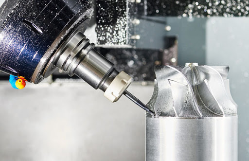
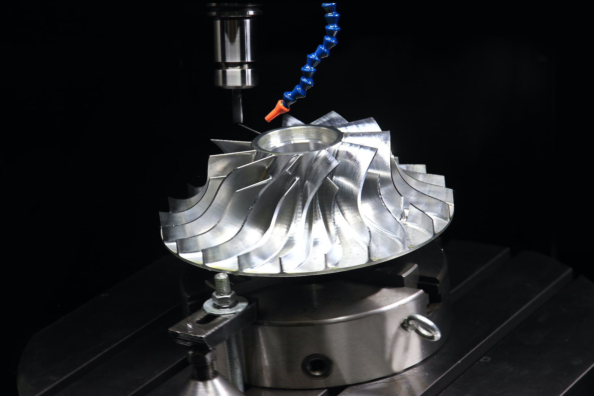
What are the commonly used clamping mechanisms?
Focus on the analysis and grasp of the inclined wedge clamping mechanism.
- Inclined wedge clamping structure
- Screw clamping structure
- Eccentric clamping structure
- Hinge clamping structure
- Centering clamping structure
- Linkage clamping structure
How to classify according to the structure characteristics of the drill die? How to classify the drill sleeve according to its structural characteristics? According to drill template and clip specific connection way is divided into which a few kinds?
According to the common structure characteristics of drilling die:
- Fixed drilling die
- Rotary drill die
- Fip drill
- Cover plate drilling mould
- Sliding column type drilling die drilling die structure characteristics classification:
- Fixed drilling die
- Can change the drilling die
- Quickly change the drill die
- Special drilling mold drilling template in the clip of the specific connection mode: fixed hinge type separated hanging type.


